Automated Connection of Chargers for Electric Cars
A camera finds the charging port of an electric car. A UR10 robot arm picks up the charger plug and plugs it in. No human touches the cable.
Gergő Kiss · supervised by Søren Hansen, DTU Electrical Engineering
Abstract
Charging cables get heavier as charging power grows. They are hard to handle for elderly and physically restricted people. Self-driving cars will need to charge without a driver. So charging has to be automated too.
This project builds a camera-based vision system that finds the charging inlet of an electric car. The system then controls a robot arm. The arm grabs the charging plug and plugs it into the inlet, using the 3D position and rotation of the inlet.
Setup
The lab cell copies a commercial charging station. The robot stands between the station's columns, with its base 735 mm above the ground. A plywood box holds the car inlet.
- Robot: Universal Robots UR10, 10 kg payload. The charging cable weighs more than 8 kg (about 2.8 kg per metre).
- Gripper: OnRobot RG2. Its standard fingers could not hold the plug, so new enclosing fingers were cut from a 30×30 mm aluminium profile.
- Camera: PlayStation Eye, 640×480 at 60 Hz, mounted on the gripper.
- Distance: two ultrasonic sensors on an Arduino UNO under the robot base.
- Target: a CCS Type 2 (Combo) inlet and plug. The inlet is uncovered. Its centre is 80–100 cm above the ground and at most 1.4 m from the robot base.
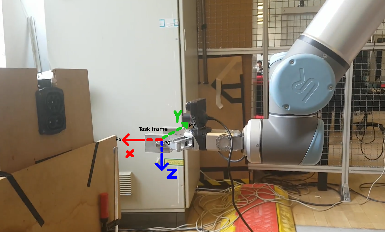
Robot
A Python and C++ client sends URScript commands (movej, movel) to the UR10 over a TCP socket on port 30003. The forward kinematics use the Denavit–Hartenberg parameters of the UR10. The tool length is 185 mm with the gripper open and 365 mm with the plug.
Scan positions are given in a task frame, then mapped to the robot base frame:
Pbase = [P0Px, P0Py, P0Px × P0Py] · Ptask + P0
The sequence
- Home — joint move.
- Before capture — joint move to a stable point, then switch to linear moves.
- Scan — 15 images in a 3×5 matrix, 50 mm apart, 360 mm from the inlet.
- Locate — the mean of the detections gives the inlet centre.
- Before grab → Grab → Lift — take the plug from its parking position.
- Before plug-in → Plug in — a linear move along the inlet axis.
- Unplug and put back — the same motions in the opposite direction.
Computer vision
The vision system is written in C++ with OpenCV. It looks for the W shape of the five AC pins: three equilateral triangles with 16 mm sides. The middle top pin lies on the symmetry axis, so it marks the inlet centre.
First layer: find circles
Fix brightness and contrast if the image is too dark. Convert to grey-scale. Apply a median blur. Then find circles in two ways and merge the results: Hough circle detection, and Canny edges → contours → minimum enclosing circles with a radius filter.
Second layer: find the W
Take every set of three circle centres. Keep the ones that form the equilateral triangle (side dm) or the isosceles triangle (base 1.7337·dm), with ±3.25 px tolerance. If only four pins are found, rebuild the fifth from the min/max coordinates. If more than five, a "fault" filter removes false circles near real pins.
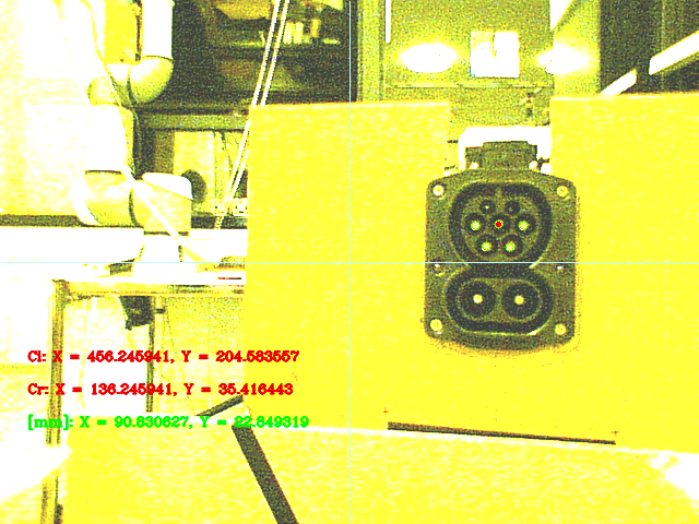
The camera was the weak point. Its pixels are large (6 µm) and its parameters are unknown, so the focal length was measured by hand (523.3 px). The pixel-to-mm ratio had to be split into a horizontal (1.41) and a vertical (1.48) value. Detections far from the image axes were more accurate, so the results were weighted by that distance.
Results
24 test runs, 15 captures each. Offsets were measured with an aluminium rod in the plug's centre hole, aimed at the inlet's centre pin.
| Test | Vision result | False positives | Offset Z | Offset Y | Offset r | Rotation | Plug-in |
|---|
Averages over the measured runs: Z 2.28 mm, Y 3.79 mm, r 4.69 mm. False-positive rate 2.58 % overall, 0 % in the final version. Plug-in succeeded in 9 of 20 measured runs, all of them in the later versions. With the inlet rotated by 5°, the offset was about 6 mm and the angle offset 3°. Note: the thesis text gives 302 of 360 captures (83.89 %); the vision column of its results table adds up to 310.
Simulation
Watch the sequence in your browser. A UR10 replays the joint targets from the original scripts: scan, grab, plug in, put back. The gripper camera view shows each capture and the same pixel-to-mm conversion.
Assumptions: no camera noise; the camera is 44 mm above the tool axis; the scan stand-off is the thesis's 360 mm.
Code
The original 2018 code, unchanged except for removed lab network details.
- robot/robot.py
- URScript over a socket: task frame,
movel,movej, gripper I/O. - robot/c.py, b.py
- Grab the plug, and put it back (joint targets).
- vision/thesis.cpp
- Final program: scan, vision pipeline, weighting, plug-in move.
- arduino/
- Two ultrasonic sensors for the distance to the car.
- sim/
- The browser simulation (new, 2026).
Conclusion and future work
The vision system finds CCS inlets and simple AC inlets reliably. The camera's resolution limited the metric accuracy, and calibration plus weighting brought the offset under the 3 mm limit.
- A better camera, with a flashlight and a distance sensor on the arm.
- A 3D-printed finger made for the plug.
- Detect the DC pins too, to tell CCS and plain AC inlets apart.
- Tests on real cars with the inlet cover.
- Faster: shorter delays between robot commands.
- A database of inlet positions per car model, linked to licence-plate recognition.